How to calculate the required number of screw piles?
The foundation is the basis of the building, and its correct calculation is the basis of the longevity of the whole building. In order to calculate the required number of screw piles, their width and other parameters necessary for the construction of the foundation, it is necessary to follow a verified standardized method. It includes a set of formulas in which it is necessary to substitute geodetic data on the specifics of a particular area and table values that correspond to the desired parameters of the foundation. In order to calculate the number of screw piles for the foundation in a private house, it is necessary to penetrate into all the features and subtleties of the calculations.
Purpose
The foundation on screw piles is an excellent solution for areas with difficult terrain, which also has a moderate price.The specificity of this technology allows the installation of supports for 3 days and at the same time guarantees the reliability of the foundation for at least 100 years. To obtain a qualitative result, it is necessary to take into account all the factors incorporated in the process: uniform load distribution, soil features, depth of soil freezing, presence and specificity of groundwater, etc.
As a result of all calculations, data appears that gives answers to such questions as:
- the required height of the screw piles;
- diameter of screw piles;
- the depth of their installation;
- the required number of screw piles;
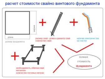
- total cost of materials.
Calculation Order
Always the first step in any job is design.
For calculations, you can use a standardized method for screw piles, described in SNiP 2.02.03–85. It is based on data from geodetic surveys of a particular plot of land.
They include the following information:
- description of the land plot;
- soil composition and density;
- groundwater level;
- soil freezing depth;
- Seasonal rainfall in the development region.
Using this data, the number of screw piles for the foundation (K) is calculated.
For the calculations will need the following indicators:
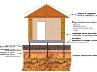
- the total load on the foundation (P), which is the sum of the masses of all the materials used;
- safety factor (k), which is a correction indicator for the total load on the piles;
- soil bearing capacity - tabular value;
- the heel area of the pile, which is directly dependent on its diameter, is a table value;
- maximum allowable load (S), the indicator for one pile is a table value.
The following is the substitution of values in the formula of the following form: K = P * K / S.
The reliability coefficient (k) correlates with the total number of piles and has the appropriate values:
- K = 1.4, if the pile is from 11 to 22 pieces;
- k = 1.65 - from 5 to 10 pieces;
- k = 1.75 - from 1 to 5 pieces.
Each pile has a load equal to the total load divided by the number of supports. The smaller they are, the stronger the load on one pile and the faster it becomes unusable, and with them the entire foundation and house.
The correct calculation is to select such a number of piles, which is enough for the entire period of operation of the structure, but without excessive surplus, which is a waste of funds.
With the help of the above formula, the coefficient for screw piles, the calculation of loads and further construction are not particularly difficult.
In the final calculations it is necessary to distribute the load under the load-bearing structures and critical points with excessive pressure on the foundation, taking into account:
- type of piles (trailing or racks);
- masses;
- values of bank effort.
Options
When calculating the screw foundation and the loads exerted on it, the following indicators should be considered:
- the total mass of the structure (constant), measured in kilograms, is the sum of the masses of such elements:
- walls and partitions;
- overlaps;
- roofs;
- additional loads (temporary, variable):
- mass of snow on the roof;
- the mass of all items in the house: furniture, equipment, decoration materials and tenants (average value 350 kg / sq. m);
- short-term dynamic loads arise from the effects of:
- gusts of wind;
- sedimentary processes;
- temperature fluctuations.
Species
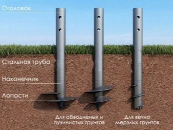
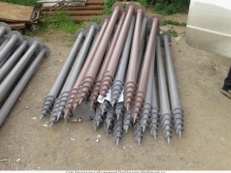
Depending on the structure (shape) of a screw pile, the specifics of its use vary.
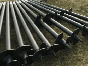
There are such common types:
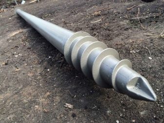
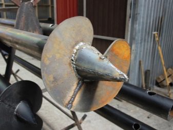
- shirokoplastnaya with a cast tip - used for small buildings with simple ground;
- multilayer with several blades at different levels - used with increased load on complex ground;
- with variable perimeter - a narrow product for specific conditions;
- narrow-layer with cast toothed tip - used in permafrost and stony soil.
Specifications
There are several basic technical characteristics of screw piles.
These include:
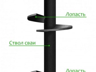
- barrel length and material;
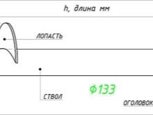
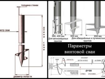
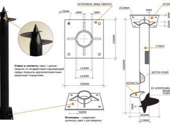
- pile diameter;
- type of blades and their method of fastening on the trunk.
Diameter
Piles are made with standardized dimensions for the execution of relevant tasks:
- 89 mm (blade diameter 250 mm) - with a calculated load on one support not exceeding 5 tons, these are mostly frame single-story houses;
- 108 mm (blade diameter 300 mm) - with a design load on one support no more than 7 tons: frame one- and two-storey houses, timber buildings and foam blocks;
- 133 mm (blade diameter 350 mm) - with a calculated load on one support no more than 10 tons: brick and aerated concrete houses using metal elements.
Length
The choice of pile length is based on the density of the soil: the pile should be based only on solid soils.
Also, their length depends on the differences in height at the site:
- loam depth less than 1 meter - pile length 2.5 meters;
- with loose soils or floating, the pile length is determined by the depth of the drill to solid formations;
- in case of uneven sections, the difference in pile length can vary from 0.5 meter or more, depending on the specific case.
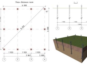
The number of supports and the interval of their location
Table values of the location of the supports relative to each other include the following values:
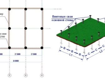
- from 2 to 2.5 meters - for houses with wooden frames and block structures;
- 3 meters - for buildings from a bar or logs.
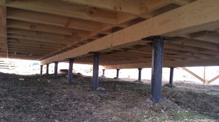
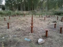
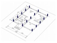
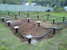
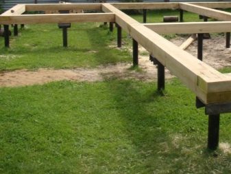
When arranging the foundation piles for uniform load distribution, the following rules for their placement should be considered:
- at every corner of the house;
- at the intersection of the bearing wall and the internal partition;
- near the entrance portal;
- within the perimeter of the building with an interval of 2 meters;
- under the fireplace at least 2 piles;
- under the supporting wall, at the location of the balcony, mezzanine or similar design.
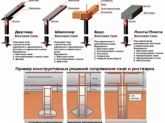
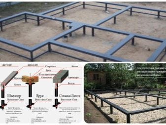
Grillage
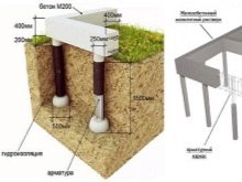
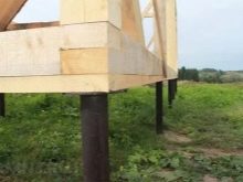
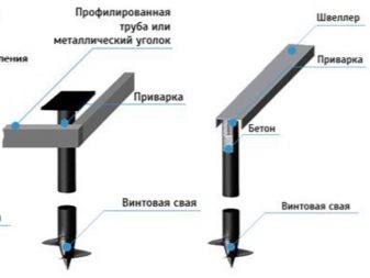
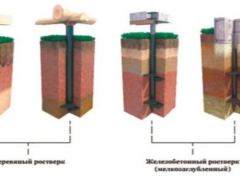
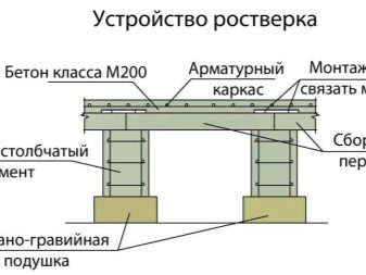
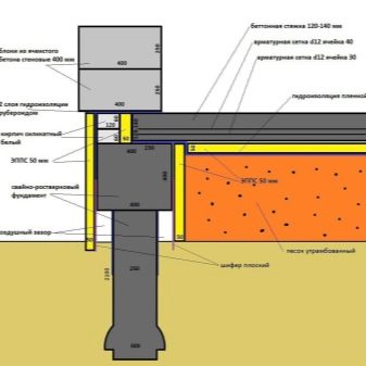
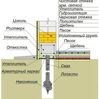
Rostverk - the foundation element necessary for uniform distribution of the load rendered by a structure on the base. To ensure the reliability of the grillage, you need to calculate a number of parameters, and the type of grillage does not matter.
The calculations include:
- force pushing the foundation;
- burst force acting on each corner separately;
- bending force.
If a high grillage is used, the entire load acts on the piles. The vertical load acts from below, the deforming load is from the side. Such calculations are very complex and require professional knowledge. For calculations it is necessary to use the standards of individual construction.
They define the following standards:
- supports can be connected with the grillage in two ways: rigid and free;
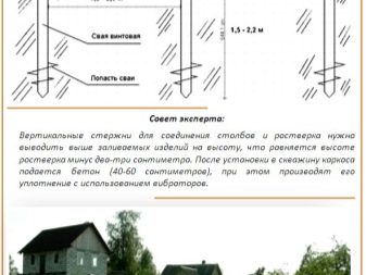
- the depth of the pile head entry into the grillage is at least 10 cm;
- the distance between the ground and the grillage is at least 20 cm;
- the thickness of the grillage can not be less than the thickness of the walls and is at least 40 cm;
- the grillage must have a height of more than 30 cm;
- the grillage is reinforced by longitudinal and transverse reinforcement with a rod section from 10 to 12 mm.
Counting example
This example serves to show in detail the use of formulas in the calculations of the pile-screw foundation.
Baseline data for a house with a 10x10 perimeter are:
- the house, built on frame technology, the roof is covered with slate, there is a porch;
- the dimensions of the foundation are 10x10, the height of the building is 3 meters;
- inside there are two partitions that, intersecting, divide the room into 3 rooms;
- roof slope - 60 degrees;
- the frame is made of timber with a section of 150x150;
- the grillage is made of timber with a section of 200x200;
- walls are made of CIP panels.
Further calculations are carried out on the following structural elements:
- wall area:
- carriers: 10 * 3 * 4 = 120 square meters. m;
- partitions: 10 * 3 + 5 * 3 = 45 square meters. m;
- mass of walls (mass of 1 sq. m. walls from timber and partitions are taken from the table of average values):
- bearing: 50 kg * 120 = 6000 kg;
- partitions: 30 kg * 45 = 1350 kg;
- total: 6000 + 1350 = 7350 kg;
- the mass of floors per 100 square meters. m .:
- ground floor: 150 kg * 100 = 15000 kg;
- attic: 100 kg * 100 = 10,000 kg;
- roof: 50 kg * 100 = 5000 kg;
- total: 15,000 * 10,000 + 5,000 = 30,000 kg;
- the mass of additional elements (internal filling of the house, the type of household appliances, finishes, the number of tenants, etc.), takes the tabular average value for 1 square meter. m 350 kg:
- 350 * 100 = 35,000 kg .;
- total mass of the structure:
- 35000 + 30000 + 7350 = 72350 kg;
- for example, a safety factor of 1.4 is taken;
- the maximum load on the heel of the pile with a diameter of 300 mm is 2600 kg, provided that the resistance of the soil is 3 kg / cu. cm (soil with medium density, deep water and freezing level is not more than 1 meter);
- calculate the number of piles according to the formula K = P * K / S: K = 72350 * 1.4 / 2600 = 39 piles.
Additional recommendations
In the process of calculating the number of piles and their distribution over the entire area of the foundation, there are many small features, each of which somehow affects the improvement of the final result:
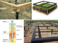
- when installing the foundation of screw piles on a complex unstable soil to reinforce the supporting structure is used piping with the use of a metal angle or channel at the level of the socle;
- in the absence of geodetic data for calculations, it is better to use the parameters corresponding to the minimum design load, that is, to create the maximum safety factor;
- to improve the quality of calculations, except for formulas and tabular data, it is worth using a program for designing: it will recalculate all the parameters and refute or confirm the manual calculation;
- the least durable piles have suture pipes with welded blades;
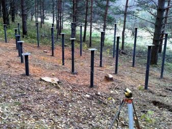
- according to the standards, the base should not rise more than 60 cm above the ground, while the pile stock in length should be from 20 to 30 cm.
The estimated number of piles is not always optimal: there may be additional circumstances that require the use of more of them.In addition, a small margin of safety favorably affects the durability of the foundation.
When installing piles in an uneven area, it is advisable to leave a margin of length in the region of 20–50 cm. In the future, the excess can be cut off or pulled out. But with a shortage - will have to hammer a new pile.
For how to calculate the number of screw piles, see the video below.
